Copyright © Françoise Herrmann
Cambridge Dictionary shortlisted and defined the following terms, all related to Artificial Intelligence, as competing entries for the Word of the Year 2025.
"slop: content on the internet that is of very low quality, especially when it is created by artificial intelligence.
pseudonymization: a process in which information that relates to a particular person, for example a name or email address, is changed to a number or name that has no meaning so that it is impossible to see who the information relates to.
memeify: to turn an event, image, person etc. into a meme (= an idea, joke, image, video, etc. that is spread very quickly on the internet.)"
Cambridge Dictionary also tracked the emergence of the following terms in in 2025, providing the following definitions and usage examples:
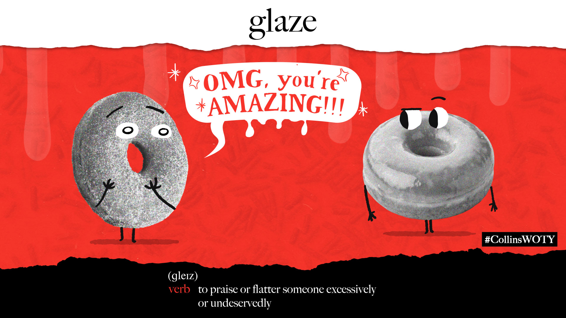
"glazing is the excessive use of praise or flattery, especially by AI chatbots, in a way that seems insincere and artificial.Example: When the chatbot’s responses lean too far into glazing, it immediately sounds my alarm bells.bias is the object of a fan’s stanning, or excessive devotion to a singer, band or other media star. It is used especially by fans of the South Korean music genre K-pop.Example: My bias is V from BTS – he has the best outfits!vibey describes a place that has a good vibe.Example: The place is vibey, has a great buzz, and is perfect for people watching.doom spending is the activity of spending money that you cannot afford in order to make yourself feel better. People sometimes engage in it when they feel anxious and uncertain about the future.Example: Although doom spending may provide short-term emotional relief, it can also have a long-term impact on your financial stability."
More than 6000 words were added to the Cambridge Dictionary in 2025. Among these new words:
"delulu: a play on the word delusional, means ‘believing things that are not real or true, usually because you choose to’.
Example: In March 2025, Australian Prime Minister Anthony Albanese used the Gen-Z phrase “delulu with no solulu” in a speech in parliament.
tradwife: short for traditional wife – ‘a married woman, especially one who posts on social media, who stays at home doing cooking, cleaning, etc. and has children that she takes care of’ – reflects a growing, controversial Instagram and TikTok trend that embraces traditional gender roles.Example: Hannah Neeleman of Ballerina Farm has been dubbed the queen of tradwifery.snackable, used to describe content that you can read or play in small amounts or for a short time, reflects our ever-shrinking attention spans.
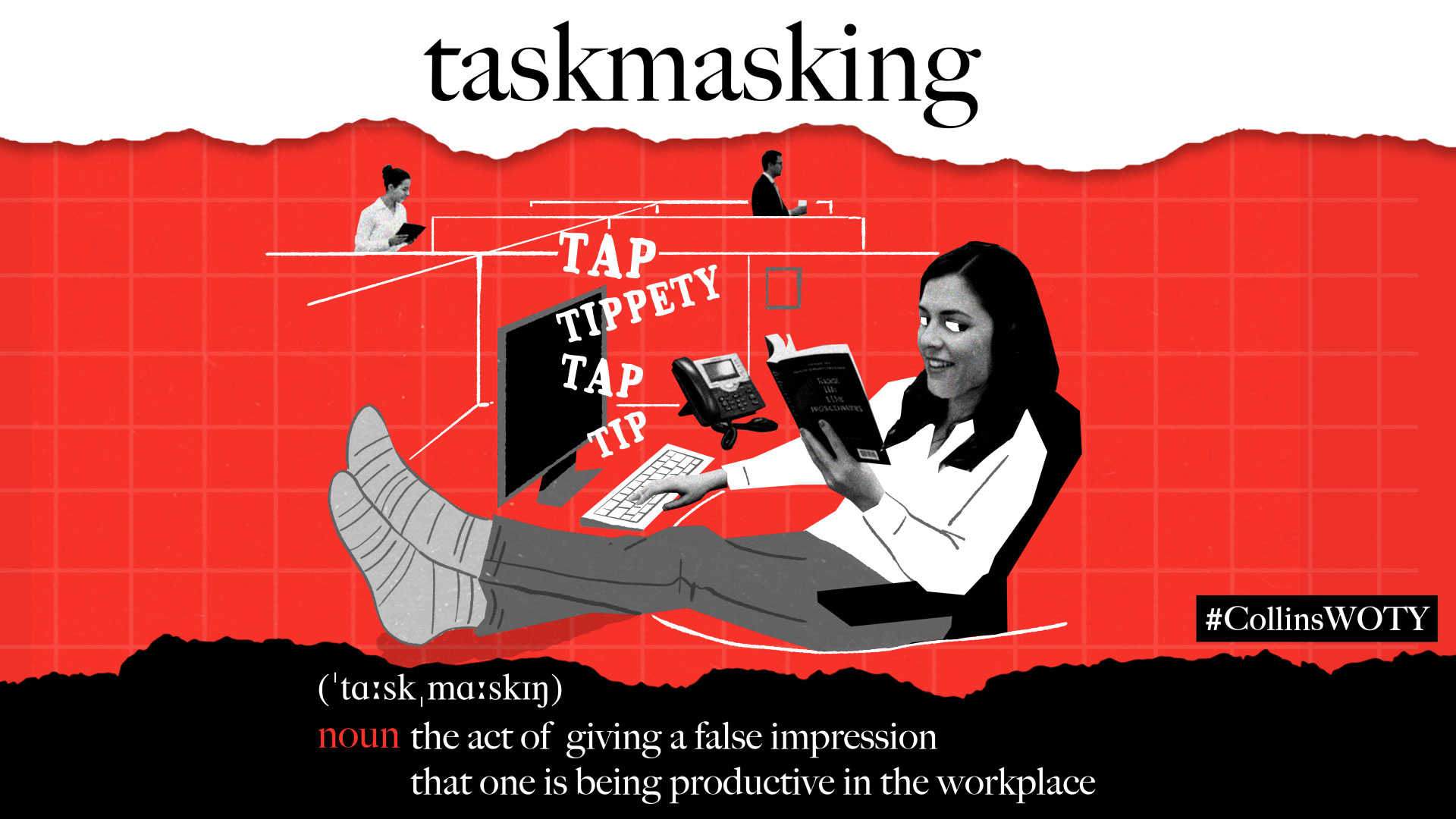
mouse jiggler, a device or piece of software used to make it seem as though you are working when you are not.
forever chemical, refers to ‘artificial chemicals that are used to make many different products, that stay in the environment for a long time and are harmful to the health of people and animals’."


