Saturday, July 26, 2025

Oh, patents! Interface for Rain Bird® wireless rain/freeze sensor

 Copyright © Françoise Herrmann

Rain Bird® irrigation systems are foremost concerned with water conservation. “Every drop counts” guides the company’s philosophy and its line of products that includes drip irrigation, and root watering systems, sprinkler systems, timers and sensors, as well as the Watersense program, in partnership with the Environmental Protection Agency (EPA). A program designed to label products that have been certified water-efficient, according to a series of efficiency and performance criteria.

The Rain Bird® wireless rain/freeze sensor is one such significant water conservation product. Connected to an irrigation system controller, the Rain Bird® wireless rain/freeze sensor immediately interrupts the irrigation cycle when certain temperature, and/or rainfall conditions have been met. Then, once the rainfall and/or temperature conditions are no longer met, the irrigation system resets to start.

The Rain Bird® wireless rain/freeze sensor interface is a patented invention. The US design patent USD623194S1, titled Graphics interface for the wireless rain sensor, was awarded on September 7th, 2010, to Carl Dennell Cook, William John Leach, and Charles S. Curbbun. The patent was assigned to Rain Bird Corporation.

The patent Figure 1 below depicts the graphical interface of the Rain Bird® wireless rain/freeze sensor interface. The Figure 1 interface displays both the rainfall cloud and the temperature ice-crystal trip indicator icons. The temperature ice-crystal trip indicator icon is displayed because the temperature has dropped below the selected threshold level. The rainfall cloud trip indicator icon is displayed because the rainfall exceeds the selected threshold level. Thus, both temperature and rainfall conditions are met, resulting in an interruption of the irrigation cycle. Rainfall settings range from 1/8” (3 mm) to 1/2” (13 mm). A setting closer to the top allows more precipitation to occur before the irrigation shuts off. Three temperature settings: 33°F (0.5°C), 37°F (3°C), or 41°F (5°C) may be selected. Selecting a lower temperature allows irrigation at lower temperatures.

An image of the marketed Rain Bird® wireless rain/freeze sensor interface is also included below. The interface in this image does not display the rainfall cloud or temperature ice-crystal trip indicator icons, as neither the rain nor the temperature conditions have been met, and irrigation is still working.

On the patent Figure 1, the broken lines for the battery indicator values, the signal strength indicator, as well as the 72-hour irrigation override indicator, correspond to unclaimed portions of the design.


References
Rain Bird® (website)
Rain Bird® Watersense Program
Rain bird® W2 Rain/Freeze sensor

Friday, July 25, 2025

Oh, patents! Rain Bird® Insertion tool

 Copyright © Françoise Herrmann

The Rain Bird® insertion tool minimizes hand fatigue when connecting drip lines with coupling, elbow, or three-way T fittings. The fitting is secured on the tool. Then, one or the other side of the tool handle is used to flare out the drip line, temporarily widening the opening, so that it is easier to insert the fitting.

The Rain Bird® insertion tool is a patented design. The US design patent, USD678016S1, titled Insertion tool was awarded to Raymond P. Feith. The patent was granted on March 19th, 2013, and assigned to the Rain Bird Corporation.

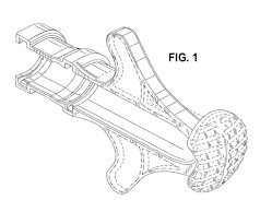
Below, the patent Figure 1 depicts a perspective view of the Rain Bird® insertion tool. An image of the marketed tool is also included, together with a screen captured sequence of how the tool works: 1. Placing a connection fitting, 2. Widening the drip line with one side or the other side of the tool and, 3. Inserting the fitting into the drip line.


1. Coupling  fitting added to tool.
2. Widening the drip line with side of tool. 
  
3. Inserting drip line on fitting

Reference
Rain Bird (website)
www.rainbird.com

Monday, July 21, 2025

Oh, patents - Rain Bird® drip irrigation pipe cutting tool

 Copyright © Françoise Herrmann

Rain Bird®, leader in the domain of irrigation systems, manufactures a drip irrigation pipe cutter, designed to slice through pipes without distorting their shape. The cutting tool has a blade attached to one handle and an anvil on the other, together designed to cooperate as a cutting jaw. The anvil is further designed to conform to the shape of a drip irrigation pipe (1/4 to 3/4 inch in diameter). A slot bisects the anvil, enabling the blade to completely slice through the conduit.

The Rain Bird® pipe cutting tool is a patented invention that was granted the US design patent, USD558553, titled Cutting tool. The patent was granted on January 1st, 2008, to Raymond P. Feith, and assigned to the Rain Bird® Corporation.

Below, an image of the patent Figure 7, together with an image of the marketed Rain Bird® drip irrigation pipe cutter. The patent Figure 7 depicts a perspective view of a partially open, Rain Bird®, drip irrigation pipe cutter.


Reference
Rain Bird
® Corporation: About (website)

Saturday, July 19, 2025

Oh, patents! Rain Bird® drip irrigation emitters

Copyright © Françoise Herrmann

Rain Bird® drip irrigation emitters, also known as “drippers”, are primarily designed to provide very small quantities of water (drips), at the base of a plant, by compensating the water pressure coming from a water source, such as a watering tube. In other words, irrigation for a plant by reducing to a drip the water flow that would otherwise normally flow from a watering tube without pressure control. Attached strategically at various intervals to a watering tube, drip irrigation emitters also each provide varying amounts of water (measured in gallons per hour [GPH]) to the base of a given plant type. Varying drips of water for each plant type, extracted from the regular flow of water in a tube, as a result of having travelled through bottlenecks, and a patented maze of tiny diversion walls, within each emitter.

Compared to overhead and underground irrigation systems, the advantages of drip irrigation are considered several-fold (Rain Bird). Drip irrigation is, above all, water-efficient, selective, and suited for small areas. Drip irrigation provides very small amounts of water to each individual plant. Water is targeted at the roots, thus discouraging weeds from growing around the plant, and leaves from molding. Drip irrigation is also easy to install, expand, and modify.

The Rain Bird® drip irrigation emitter is a patented invention, covering the design of a small irrigation device (<1 inch), resistant to the fast flow of normally running water, usually inside a .5 or .75-inch watering tube. The US utility patent, US5820029, titled Drip irrigation emitter, was awarded on October 13th, 1998, to Elaine Marans. The patent was assigned to Rain Bird® Sprinkler Manufacturing Corp.* in Glendale, California.

Included below, the patent Figure 2, with the images of two marketed Rain Bird® drip irrigation emitters, a blue half-gallon emitter and a red two-gallon emitter. The patent Figure 2 is an exploded view of the Rain Bird® irrigation emitter 10. The patent Figure 2 depicts a cup-shaped base 20, with a circular floor surface 32, and a cylindrical upstanding outer wall 34. The circular floor 32 comprises a channel pattern 26, designed to divert (and thus reduce) the incoming flow of water, causing the water to exit as "drips" from the downward hollow stem 36. Above the channel-patterned diversion 26, on the floor surface 32, spacer posts 38 are designed to support the cap 22, which fits inside the cup-shaped base 20, together with the valve 28 beneath.


The abstract of the Rain Bird® drip irrigation emitter is included below.
An improved drip irrigation emitter is provided for low volume supply of water at a trickle or drip flow rate. The emitter comprises a housing adapted for connection to a water supply hose, and includes a water inlet and a water outlet with an elongated pressure reducing flow channel extending therebetween. The flow channel is lined on opposite sides by a plurality of flow diverting ribs which project laterally and partially into the flow channel in a staggered or alternating pattern, in combination with a plurality of flow diverting weirs which project upwardly and partially into the flow channel from a floor thereof. The flow diverting ribs and weirs define a three-dimensional tortuous flow path for repeated back-and-forth and up-and-down directional flow change as water travels therethrough, resulting in an improved pressure drop between the water inlet and outlet. [Abstract US5820029A]
Note
* The Rain Bird Manufacturing Corporation, founded in 1933, is a privately held company, currently a global leader in the domain of irrigation systems, serving 123 countries. The company holds hundreds of patents.

References
Rain Bird Corporation
Rain Bird – Five advantages of drip irrigation.

Monday, July 14, 2025

Oh, patents! Diane von Fürstenberg bag with tablet holder (2)

 Copyright © Françoise Herrmann

The Diane Von Fürstenberg (DvF) bag with tablet holder was also awarded a US design patent. In other words, a patent that covers just the ornamental aspects of the bag, in contrast to a US utility patent, covering the bag's functionalities.

The US design patent, USD728925, titled Bag with tablet holder, was awarded on May 12th, 2015, to Diane von Fürstenberg. The patent Figures 1 andare included below, respectively depicting the front and closed rear of the bag. Beneath the patent figures, an image is included of a marketed bag with tablet holder, showing the front and open rear of the bag. 


Reference
Diane von Furstenberg (website)
https://www.dvf.com

Sunday, July 13, 2025

Oh, patents! Diane von Fürstenberg bag with tablet holder (1)

 Copyright © Françoise Herrmann

The Diane Von Furstenberg (DvF) “bag with tablet holder“ was more than a tablet carrier. It was designed to enable using and viewing a tablet secured within the bag. The DvF bag with tablet holder not only resolved the prior art problems of having to haul around a second bag to accommodate a tablet. The DvF bag with tablet holder also resolved having to constantly take the tablet in and out of a bag, to see or use the device. The assumption in both cases, based on observation, was that everyone was using a tablet, and in need to consult their device several times during the day. 

The US utility patent application reciting this invention, US20130206527A1, titled Bag with tablet holder, was published on August 15th, 2013. The inventor on record is Diane von Fürstenberg.

Figure 3, extracted from the patent, is included below. The Figure 3 depicts a rear perspective of the bag with tablet holder 10, detailing the actual tablet holding aspects of the invention. 

Specifically, the Figure 3 shows the body 12 of the bag 10, with a strap 16, and the top of the front flap 14On the rear of the bag, the Figure 3 shows the device compartment 50, forming an open window 48. The tablet access flap 40 is open, with open zippers on the right 46 and on the left 44, and exposed male 56 and female 58 closure snaps. On each side of the open window 48, there are tablet panels 52, which might be padded to secure the tablet within the compartment 50. One of the side panels 52 depicts a half-circle notch, designed to accommodate the “home” button on former iPad® tablet models. The tablet compartment 50, might be accessed via a top rear opening 32, equipped with a zipper 42.


Below, an image of Diane von Fürstenberg, presenting her DvF bag with tablet holder. On the left, the image shows the front of the bag. On the right, the back flap is open, showing the  tablet inside its compartment, accessible for use.  


The invention abstract is included below. 

Disclosed herein is a bag with tablet holder that includes a body defining an inner compartment, a tablet pocket on the body defining a device compartment, a top opening defined by the body providing access to the inner compartment, and a rear opening to the tablet pocket providing access to the device compartment. An access flap extends from an edge of the tablet pocket and is movable between a closed position where it is secured over the pocket, and an open position where the pocket is uncovered and tablet is accessible. The device compartment includes a plurality of retention panels forming a border configured to receive and retain an electronic tablet in the pocket. The tablet can be accessed and used  while remaining within the pocket in the bag. [Abstract US2013/0206527A1]

Reference

Diane von Fürstenberg (website)

https://www.dvf.com

Thursday, July 10, 2025

Oh, patents! Diane von Fürstenberg Stephanie hobo

Copyright © Françoise Herrmann

Launched in 2009, the slouchy Diane von Fürstenberg Stephanie hobo became a cult favorite, used by celebrities. The medium-sized Stephanie hobo was a carry-all, measuring 14" x 22". The most popular versions were made of woven metallic-covered leather. Various models were fabricated in metallic denim, black, gunmetal metallic leather, and chainlink leather in silver/gold/black/grey and pewter with suede accents.

The Stephanie hobo was a patented design. The US design patent, USD630014, titled Bag, was awarded on January 4th, 2011, to Diane von Fürstenberg, Beatrice McCabe, and Julie Peelo.

Below, a right-side view of the Stephanie hobo, together with an image of one of the marketed models.


Reference
Diane von Fürstenberg (website)

Sunday, July 6, 2025

Oh, patents! Diane von Fürstenberg medical gown

 Copyright © Françoise Herrmann

A hospital gown designed by a well-known fashion stylist? Yes, a hospital gown designed by Diane von Fürstenberg, celebrated for her iconic wrap-around dresses, chairwoman of the Council of Fashion Designers of America (CFDA) from 2006 to 2019, and inducted into the National Women’s Hall of Fame in 2019, among many additional accolades.

The US utility patent, US8990966, titled Medical garment, was awarded to Diane von Fürstenberg, Erin Przekop, and Jeanne M. Ryan, on March 31st, 2015, and assigned jointly to Diane von Fürstenberg Studio L.P., and The Cleveland Clinic Foundation. Although the patent is a utility patent vs. a design patent that would otherwise cover only the ornamental aspects of the gown, the patent explicitly addresses both functionality and appearance. The functionality of being able to easily access a patient’s body for examination. The attractiveness of a gown that might be comforting to patients, while still providing coverage. Most importantly, an inventive gown that might also be fastened by patients without assistance, since the patent states that most hospital gowns are inspired by 19th-century night shirts, further tailored in a variety of ways to open and close in the back.

Commissioned by the Cleveland Clinic to design a gown, Diane von Fürstenberg (2021) stated: “ I was taken aback. I thought, “Why?” But then I understood: It’s about the dignity of the patient.” Fürstenberg then explained that she designed a print and worked with the hospital nurses on the gown’s functionality. In particular, she mentions that the gowns come in three sizes that are color-coded so that the correct size might be easily grabbed in a hurry.


The patent Figure 1, shown above, depicts a plan view of the inventive garment or gown 11, comprising three substantially rectangular panels, one central panel 12, and two side panels 13 and 14. The central panel 12 has a right edge 12c, and a left edge 12 b, respectively joined via the right seam 17, and the left seam 16, to the side panels 13 and 14.

The gown comprises two sleeves, a right sleeve 21, and a left sleeve 18, attached to the central and side panels (11-14) through the right and left armholes 22 and 19. The two sleeves 18 and 21 further comprise corresponding slits 36 and 37, secured with fasteners 38, to enable access to the patient’s arms.

The gown also comprises a V-neck 39, which may be worn on the front or on the back of a patient's body. When the gown is worn with the V-Neck 39 on the front, the pocket 41 appears on the patient’s chest. When the V-neck 39 is worn on the back, the pocket 48 appears on the patient's chest. The gown comprises two more pockets, the side pocket 32 attached to the seam 16, and the side pocket 33 attached to the seam 17.

The gown further comprises a tunnel-like waistband 23, extending across the left panel 13 and the central panel 12. A first belt 24 is anchored at point 24a on the seam 16, and extends out of the waistband 23, through the side panel 13. A second belt 26 is anchored at point 26a, also on the seam 16, but it extends out of the waistband 23, through the central panel 12. Both belts 24 and 26 cooperate like drawstrings to cinch the waistband 23. Two additional ties 28 and 27 are provided, respectively attached to the outer edge of the side panel 14, and to the seam 16, both at waistband 23 height. The ties, 28 and 27, are meant to coordinate with the cinching drawstring belts, 24 and 26.

Although the gown is described as a medical gown for use at hospitals, nursing homes, doctors’ offices, and other healthcare facilities, the scope of the invention is recited as extending to health spas, beauty salons, as well as to private uses, or to uses requiring the functionalities of the garment. In terms of materials, the patent recites multiple suitable materials, such as natural or synthetic fabric. Synthetic fabric unlimited to polyester, acrylic, polyamide or polyolefin fiber and combinations, provided that both the materials and the tailoring can sustain the rigors of use and multiple washing.

The patent abstract is included below.
A medical garment formed of a central body region and two side regions with a pair of belts and a pair of fasteners for securing the garment around a patient’s body is provided. The central body region may be worn on the back or front and may have a V-neck form. A waistband extends across the central body region and across one side region with a first belt secured at the junction of the central region and the second side region and extending to the outer edge of the first side region. The second belt extends from the secured end of the first belt through the waistband across the central body region, the second belt exiting the waistband at the junction of the second side region and central body region. A first fixed tie is positioned at the outer edge of the second side region along the position of the waistband. A second fixed tie is secured to the inside of the waistband between the central body region and first side region. This garment design allows for easy gathering of fabric to present a secure and attractive body covering. [Abstract US8990966]

References
Council of Fashion Designers of America (CFDA)
Cleveland Clinic
https://my.clevelandclinic.org/
Diane von F
ürstenberg (website)
www.dvf.com
Luthra, S. (March 30, 2025). A new unusual Diane Von F
ürsetenberg gown. The Washington Post.